II - Design #
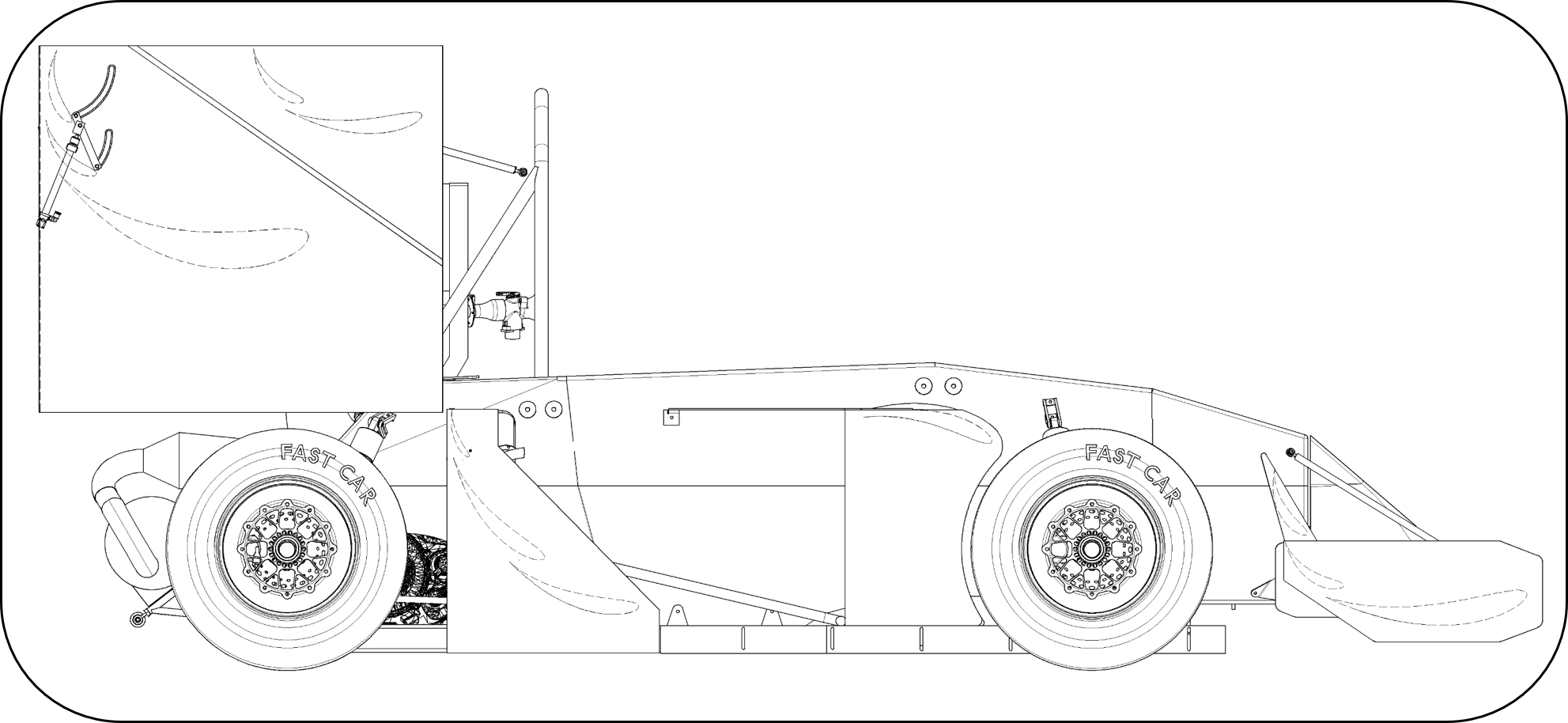
Technical drawing of GFR17c.
Introductory Thoughts #
The goal of GFR is to win every competition it enters. Therefore, each racecar is built to maximize points scored at competition under the monetary, time, and resource constraints of the team.
Through steady state lap time simulation and on-track testing, it’s possible to coarsely determine the sensitivity of various vehicle parameters to scoring points at competition. This process indicates that developing the aerodynamics package is a wise investment of time and energy.
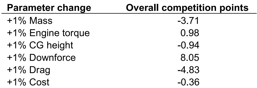
Output from a steady state lap time simulation.
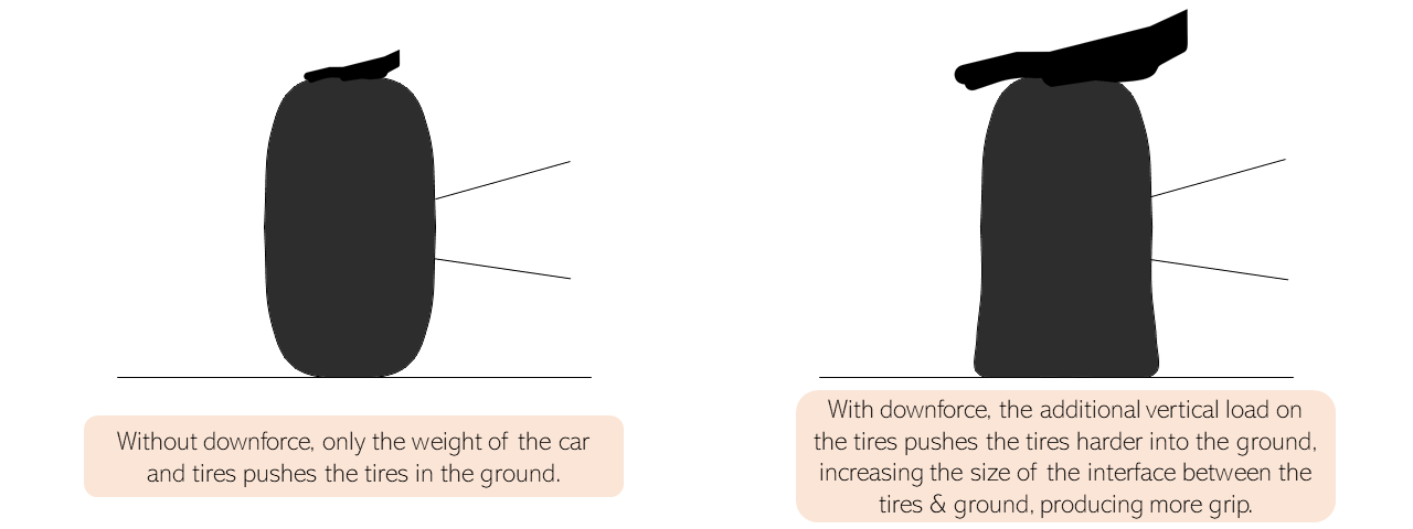
Downforce creates additional (inertia-free) vertical load on the tires, driving them harder in the ground to produce more longitudinal and lateral grip. This comes at the cost of drag, a force which effectively saps engine power. Fortunately, downforce production often greatly outpaces the drag increase.
Realizing the massive importance of a competent aerodynamics package in achieving success in the FSAE competition, I dedicated most of my efforts in that area, developing the requisite knowledge of fluid dynamics, simulations, and composites required to give the team a competitive edge.
Small Box #
Historically, the aerodynamics of FSAE cars have been largely unrestricted. As teams realized the importance of aerodynamics development, the development arms race began to get out of hand, with the speed of the cars rapidly increasing.
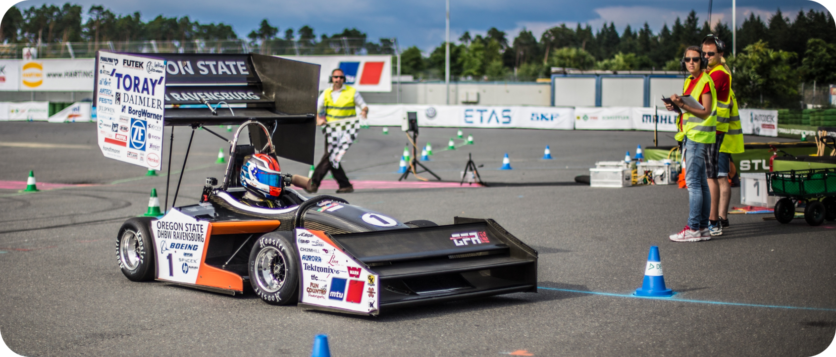
GFR14c at Formula Student Germany 2014, the last GFR car built under the largely unrestricted aerodynamics rules set. Photo courtesy of Formula Student Germany - media team.
As a result, from the 2015 season onward, the aerodynamics were curtailed via highly restrictive regulations, giving designers a very tight box to work within.
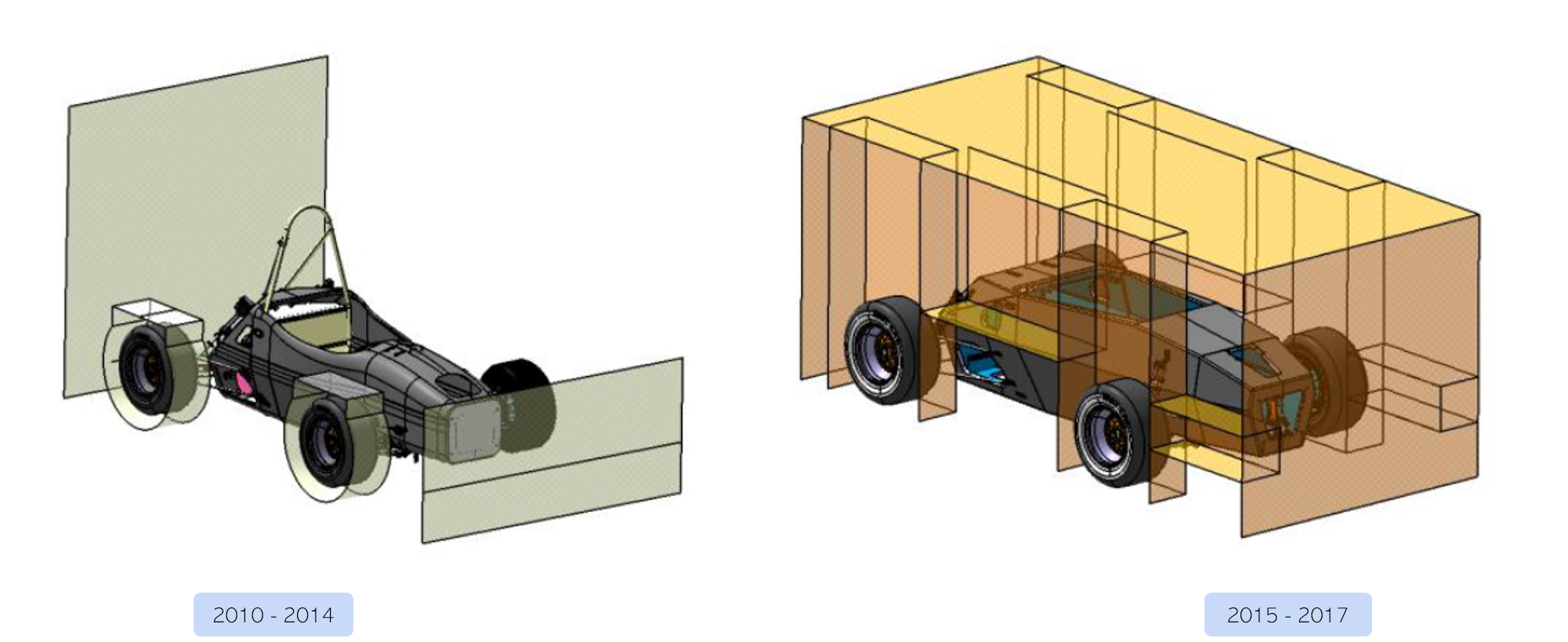
CAD (CATIA V5) representation of the different aerodynamics rulesets, with the boxes representing zones where aero devices are not permitted.
Computational Fluid Dynamics #
The primary tool for analysis is computational fluid dynamics. The geometry and fluid domain are discretized, and the fundamental equations are solved in each cell iteratively. Eventually, the model converges to a solution. There is much more complexity in the setup of a CFD model, but that is beyond the scope of this discussion. In my work, I used Star-CCM+, widely regarded as the gold standard for fluid simulation software.
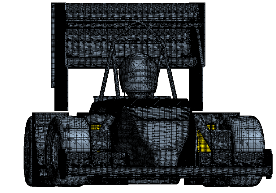
The mesh generated from Computational Fluid Dynamics (Star-CCM+).
Aerodynamic Design #
For a novice aerodynamicist, the learning curve is steep. Much of the tribal knowledge of aerodynamics design for open wheel racecars is contained within motorsport teams, under lock and key. Therefore, to build a knowledge base, development consists largely of foraging for clues in any available literature, and rapidly iterating to explore as much of the design space as possible.
Like most people diving into the deep end of something new, I started off hopelessly lost. However, the name of the game is stick with it, and eventually you start to figure things out.
Using the previous years car as baseline (GFR16c), a handful of design targets were outlined:
Design Target 1: At least 75% of vehicle weight in downforce at average speed of 65kph (40mph). This was a rough target consistent with the typical performance increase from year to year under a stable rule set.
Design Target 2: Passively cool the car at ambient temperature of 110°F. Due to the powertrain change going from the 2016 to 2017 season, active cooling (via fans) could not be relied on. This represented a significant hurdle.
Design Target 3: Increase high speed stability over the 2016 design. The 2016 car oversteered frequently, leading to low driver confidence which ultimately sacrificed lap time.
In a system of any sort of intricacy, all of the geometries are coupled together into a complex & interconnected aerodynamics system, meaning nothing can be designed in isolation. However, each area of the car has its own unique considerations.
Front Wing #
Most of the development effort on a racecars aero package is spent on the front half of the car, as it sets up the flow conditions for the back half. Therefore, when developing the front wing, it’s important to balance the need for producing ’local’ aero load with the need to create a favorable flow field for downstream performance.
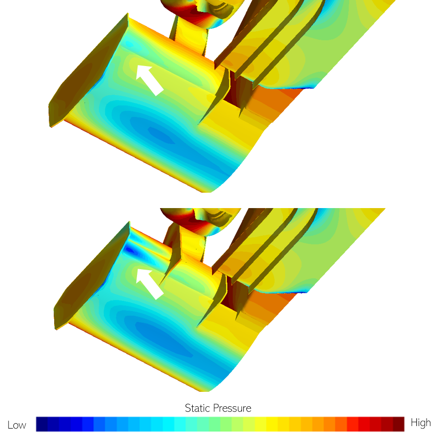
Downforce is produced by maximizing the static pressure differential on the top & button surface of the geometry.
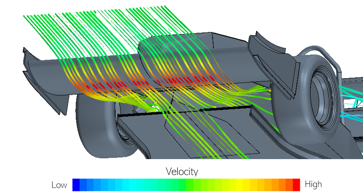
This particular front wing design works well locally, but adversely affects downstream performance by significantly reducing underbody mass flow, ultimately being an unfavorable concept.
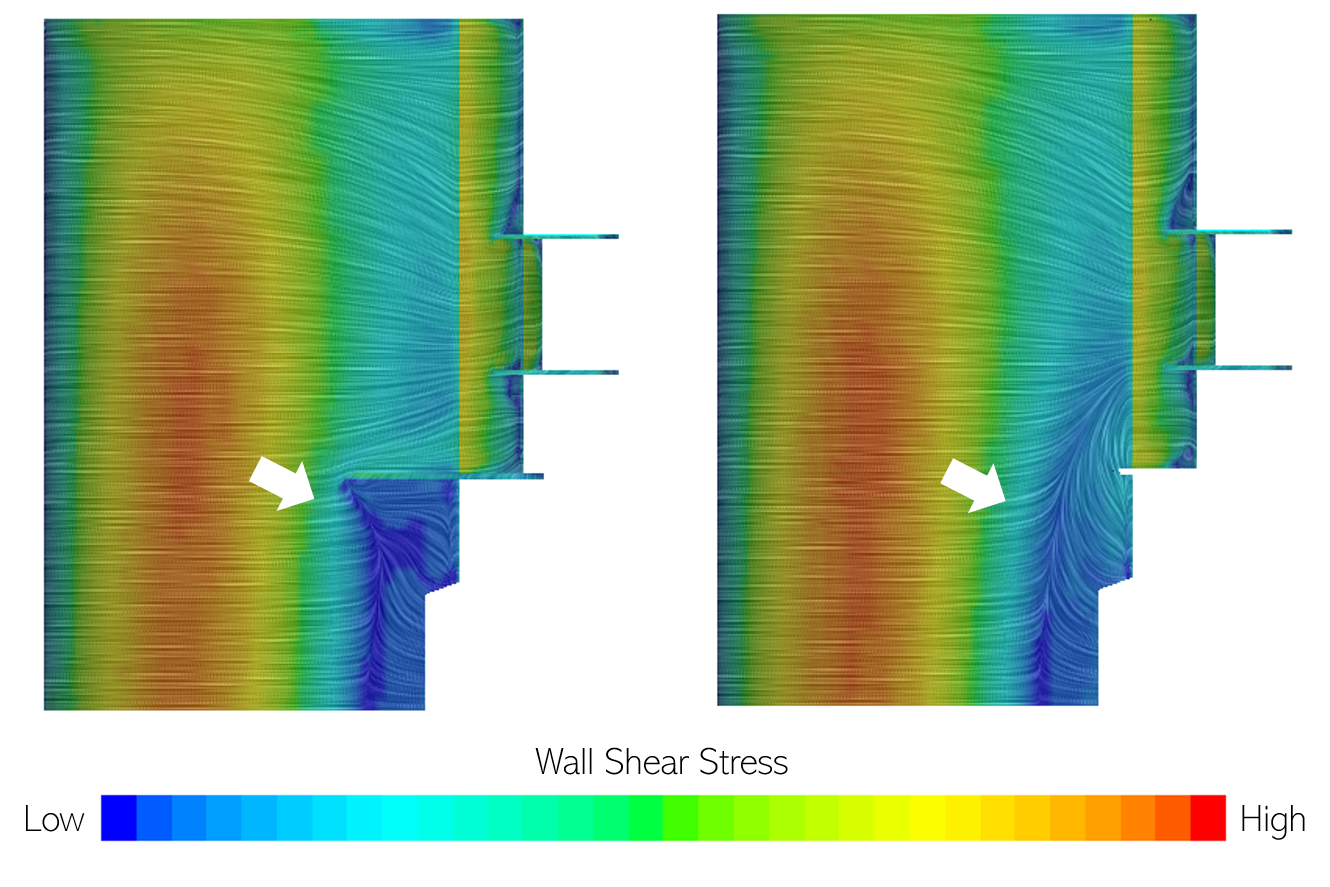
Wall shear stress on two designs. The wall shear stress represents the ‘friction’ generated by the near surface flow, and can provide hints about flow detachment.
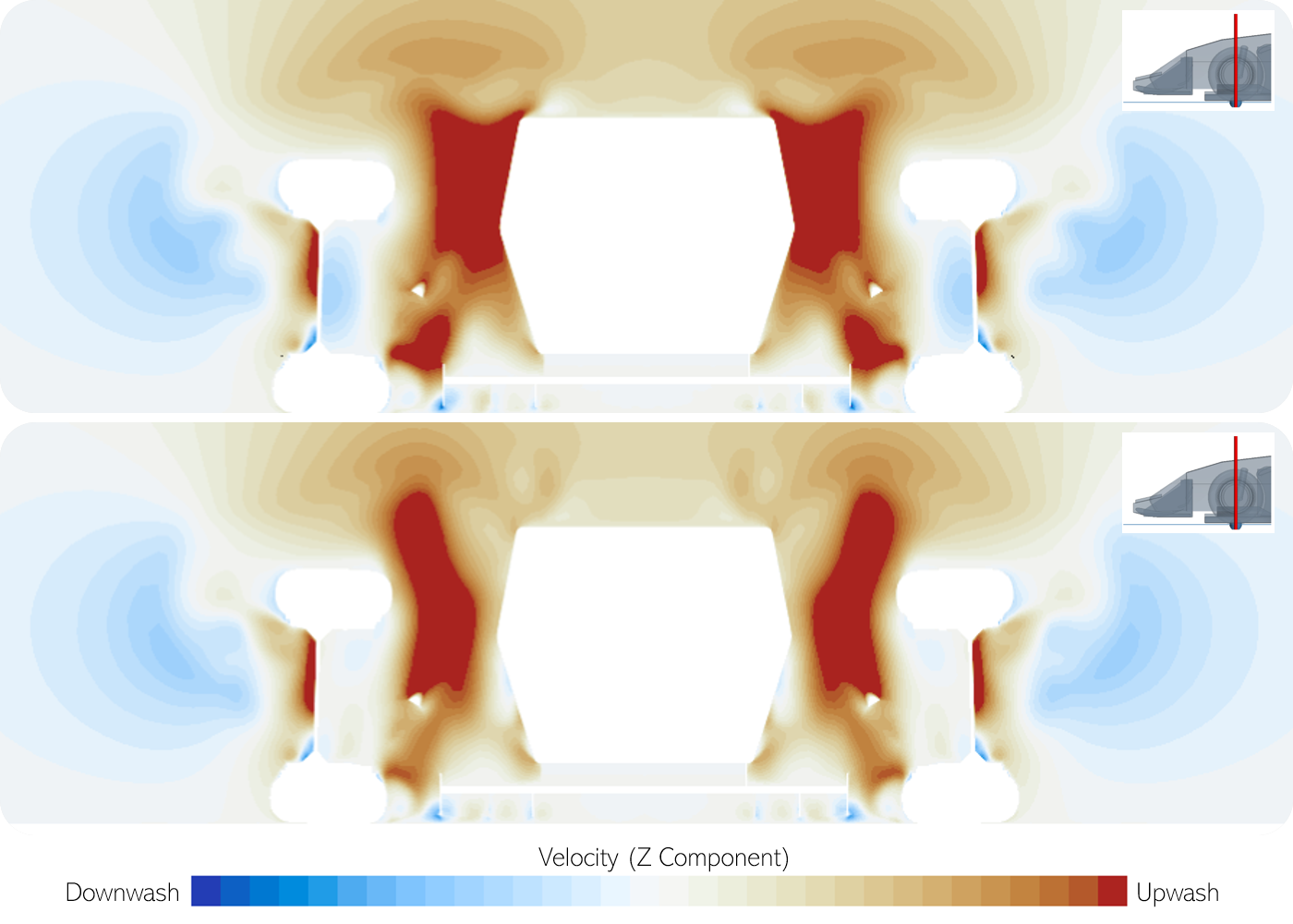
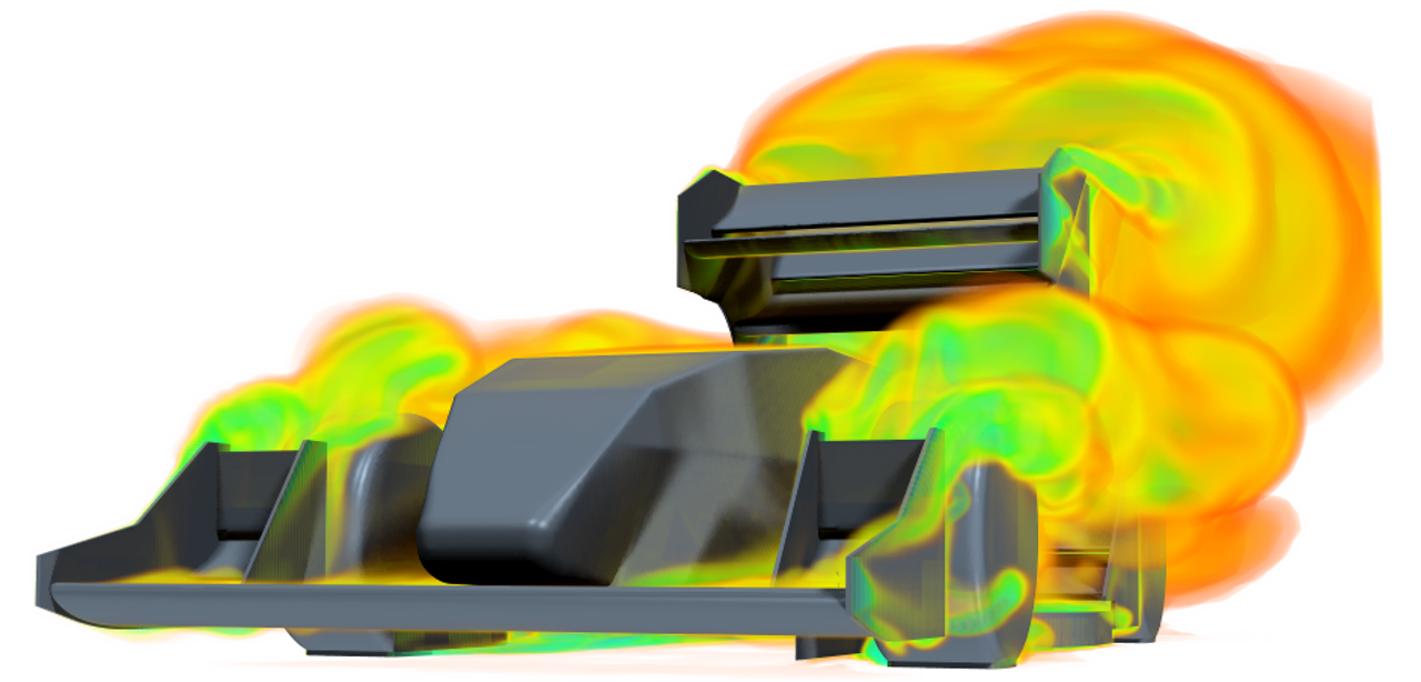
X-slice displaying the Z (Up/Down) component of the flow velocity after the front wing. This is important data to assess as too extreme an Vz will drastically reduce the incident angle of attack of downstream surfaces, reducing performance.
Side Wing/Undertray #
While the rules significantly curtail the frontal area that can be used for bodywork, planar area remains quite open. Logically, one should maximize planar area to exploit ground effect. However, there are a handful of hoops to jump through to successfully realize that theoretical performance:
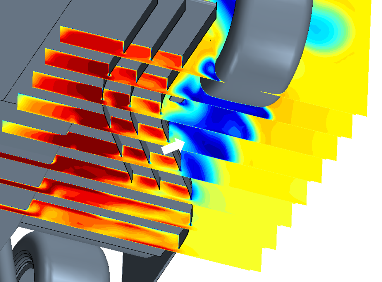
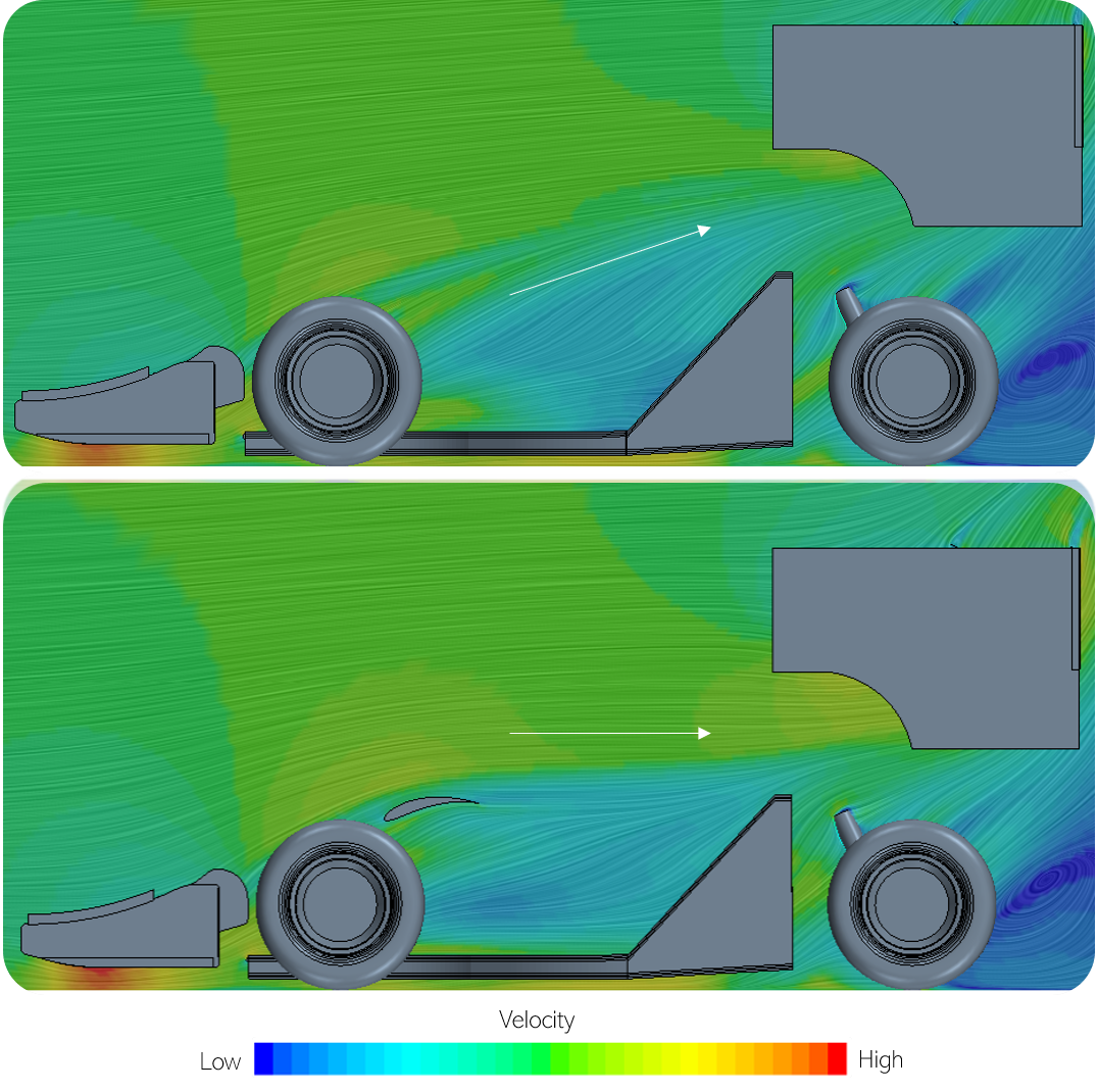
The flow that interacts with the rotating tires (‘Tire wake/jet/squirt’) adversely effects the underbody flow field. This low energy flow should be navigated out and away from the car so that it does not influence the underbody.
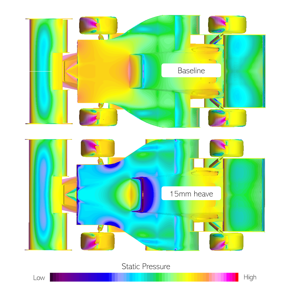
This demonstrates the effect of heave (linear vertical up/down motion of a vehicle). A racecar does not remain in a static position around a track, it is constantly yawing, pitching, rolling, and heaving. These are all important attitudes to characterize. With its massive planar area in ground effect, the undertray is highly sensitive to vehicle attitude. Designing the undertray to minimize sensitivity to attitude changes is difficult, but important, as a driver is fastest in a car that is predictable.
Rear Wing #
The rear wing not only produces considerable load, but it also helps to aerodynamically balance the car. With the rules creating a car that is fundamentally rear downforce limited, it’s important to realize maximum performance in the given box.
The rear wing is greatly effected by upstream upwash (flow with a positive Z component). Upstream bodywork can be used to reduce this effect.
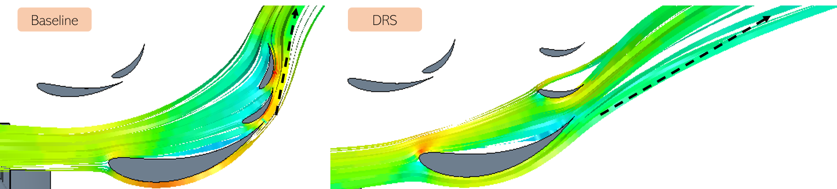
The rear wing produces a considerable amount of drag. A driver-controlled pneumatic drag reduction system (DRS) was implemented to be used on the straights to reduce flap angle. This minimizes the adverse effects of drag.
Cooling #
The cooling system effects the performance of the car through:
-
The mass of the system.
-
The airflow influencing the cars aerodynamics.
-
The location of the system influencing car CG and/or polar moment of inertia.
Most importantly, an adequate cooling system is necessary to assure the reliability necessary to complete all of the events at competition. As the heat exchangers require adequate airflow to function, the cooling system falls within the domain of the aerodynamicist.
GFR16c vs GFR17c cooling systems. For 17c, the heat exchangers were relocated to the side of the car from behind. This was due to the much higher air mass flow available on the side of the car. Additionally, centrally mounting the heat exchangers provides a more favorable total system mass, in addition to a lower polar moment of inertia.
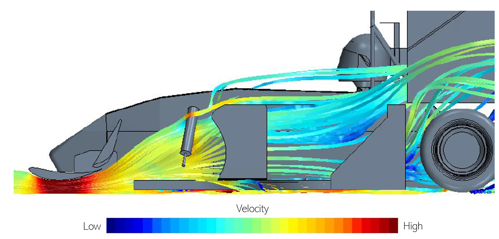
Streamlines displaying the origin of the flow passing through the heat exchanger.
Workflow #
While often not a glamorous part of the engineering process, raw throughput of concepts into the design/simulation/analysis churn directly impacts the quality of the final design. Therefore, increasing throughput of ideas is often as important as the quality of the ideas themselves, especially when novice engineers are involved. In service to this, I wrote Java macros to significantly automate case setup and post-processing. Eventually, I was able to reduce my involvement in setting up each simulation from roughly 1 hour to 10 minutes.
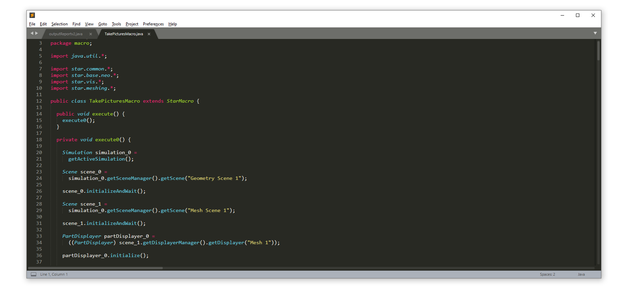
Java script to automate Star-CCM+ workflow.
Lessons Learned #
Undertaking a design project like this teaches a young engineer a lot of important lessons. In this case, the most important were derived from the various mistakes made along the way:
-
CFD, especially at the level of FSAE, should be used as a coarse guide to design, and not gospel. Therefore, provisions for adjustability should be built into the aero package. The designer is unlikely to predict the exact separation angle of a wing element from CFD. You may be able to get it 80% of the way there, but you need track testing to really dial it in.
-
RANS (steady state CFD) is commonplace for FSAE CFD. However, the flow around an open wheel car is not steady state. Even though developing in DES (transient simulation) is much more computationally intense (10x runtime of RANS), it’s probably worth it.
-
Every high quality concept should be run across multiple relevant attitudes. I spent too much time doing straight line development, assuming it was a reasonable proxy for cornering performance. This wasn’t too poor of an assumption on the ‘big winged’ cars of old, but the 2015+ ruleset created cars highly sensitive to attitude. Each attitude should consist of some amount of roll & yaw.
-
Performance shouldn’t be defined by just one downforce number at a particular attitude. It should be a weighted average across several important attitudes, likely 3-4 attitudes informed by on-track data. Testing each concept at various attitudes prevents adverse behavior from sneaking in unnoticed.
-
It’s easy to get fixated on specific flow details seen in CFD. These may not even exist in reality, and if they do, they may be difficult to control. Chasing this sort of thing wastes a lot of time.
-
Often times, the purpose of a racecars suspension is largely to maintain the aero platform. The aerodynamics and suspension teams should have a close relationship from the onset, rather than trying to come together late in the process.
-
At some point, you need to account for geometry that will occur on the real car (mounting, brackets..etc) and make sure they won’t compromise your design. Do at least a baseline analysis before disregarding certain aerodynamic factors as negligible. The consequence of them not being negligible, and realizing that late in the design process, takes much more effort to resolve.
Ultimately, I ran over 300+ external aerodynamics simulations in Star-CCM to develop the aerodynamics package of the 2017 cars. All of the design targets were met before closing the book on the design process, and starting with the manufacturing.